After a long wait I’ve finally got my hands on the ImmersionRC Vortex 250-class race quad. First order of business – tear it apart and see what we’re working with!
But first, what is it? The Vortex is a prebuilt ready-to-fly (less RC and VX receivers, so ARF to be precise) 285mm quad designed for the race scene. The frame is mostly carbon fiber with molded plastic connecting parts. It feels strong and it even came with a pack of what looks like a replacement for each of the plastic parts. All four arms fold towards the rear which makes for a really compact package.
So what do we have under the hood?
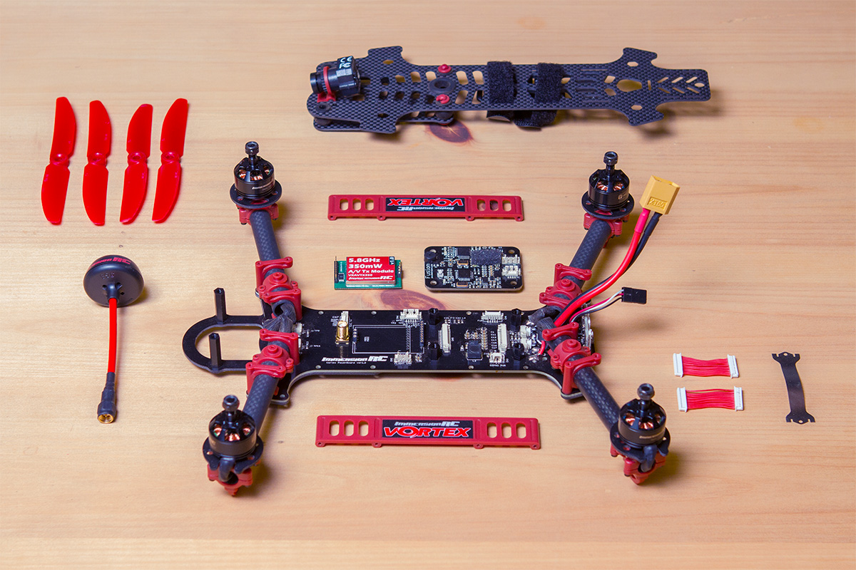
Here we go! Nothing complicated about getting it apart. You’ll notice the included CMOS flight camera is attached to the top plate on its own separate dampened plate. It’s got a hinge mechanism so you can tilt it to your flying preference.
You may notice the lack of ESCs. Immersion designed them small enough to fit inside of the arms.
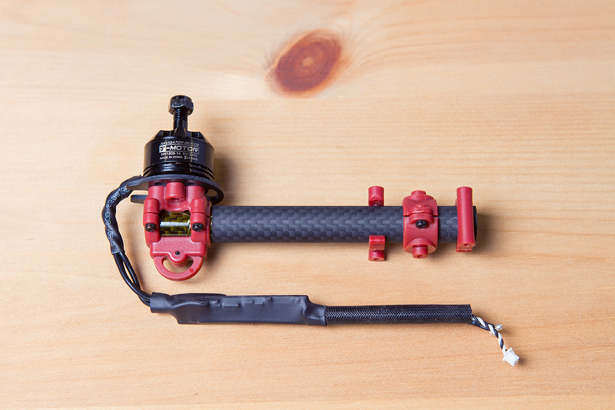
It’s super slick, but I’m a little worried this will make them hard to replace if replacements become hard to find. (By the way, my Vortex came with 2300kV T-Motors, model MN1806-14). Notice the Kapton tape under the motor mount? Maybe it helps the grip…
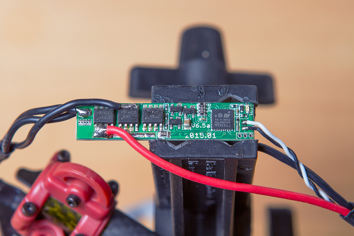
Here’s one of the ESCs exposed. They’re directly soldered to the motors on one side and to the base plate of the quad on the other. The Immersion website says these are fully custom, so I don’t think they’re based off any common ESC type. They’re powered by an STM32 ARM processor and 17 Amp MOSFETs.
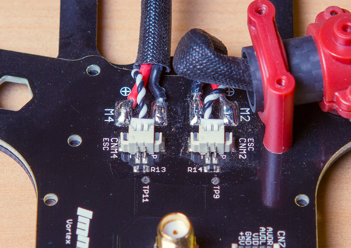
Here’s how the ESCs are connected to the base. The signal wire is connected with a plug, but power is soldered directly. It wasn’t hard to de-solder these, so I think they made a good choice doing this instead of using bulky connectors.
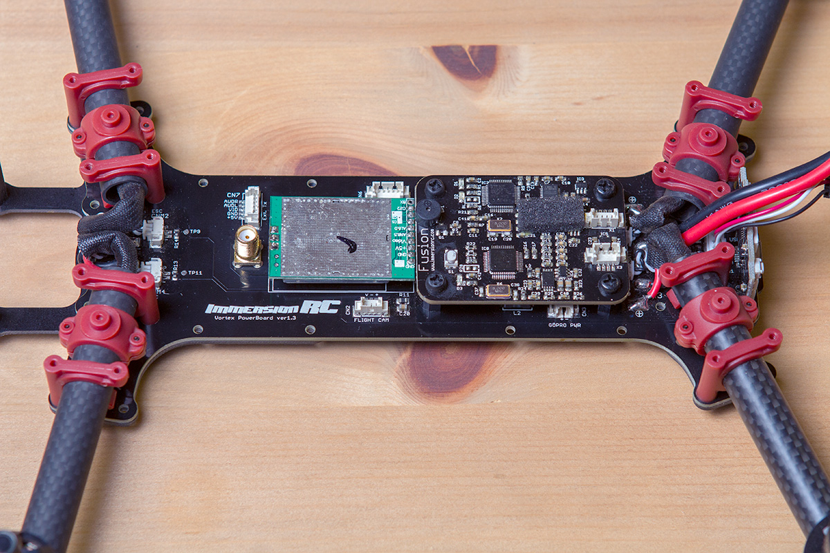
Okay, with that arm re-installed now we see where the magic happens! We’ve got two boards attached to the base – one is the video transmitter and the other the flight controller. The base serves mostly as connection between components and power distribution. There are some passive components there but nothing that really does anything.
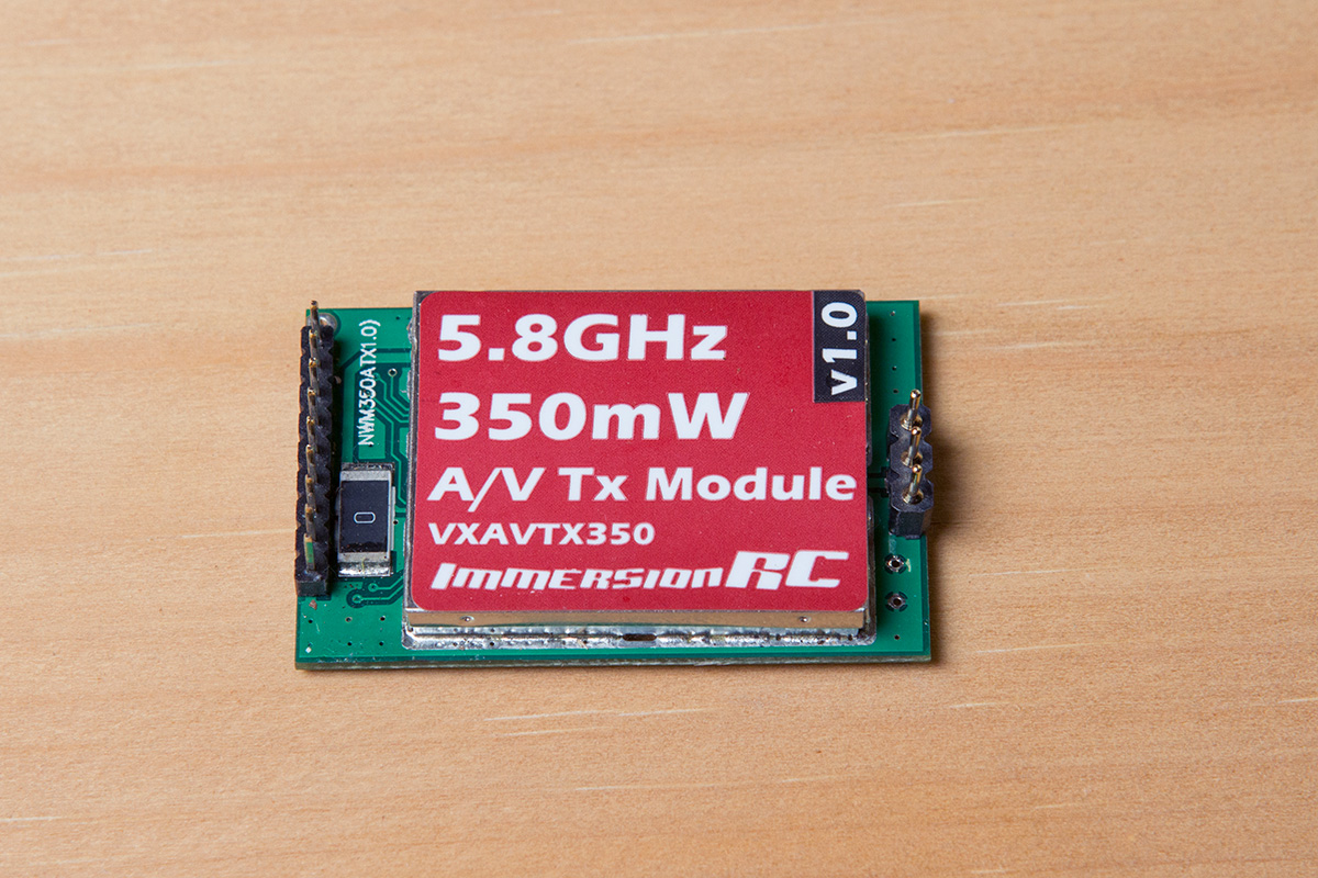
Ah! The heart of the FPV experience. A 350mW 5.8GHz transmitter. It plugs directly into the base and is held in with a kind of spring clip that pushes down on it from the top plate of the quad.
I didn’t get a photo, but there is a connector on the base board labeled “Ext. Tx” with labeled pins in case you want to remove the included video transmitter and use a different one. I may do this with my 1.2GHz gear for some long range flights.
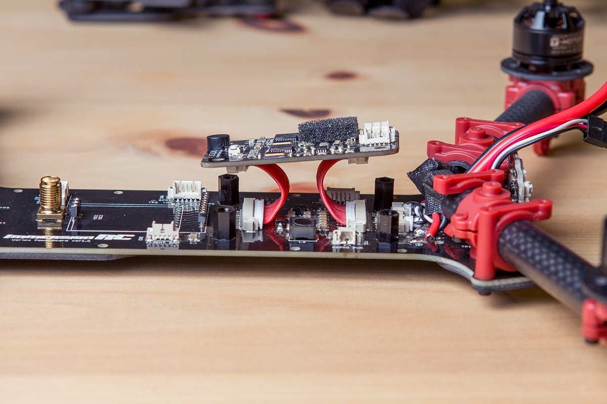
Now we’re talkin’! As you can see, the flight controller is held in place atop nylon standoffs. It’s connected with two short 12-wire connectors. I’m curious why they didn’t use pin headers on this one, but it seems well enough.
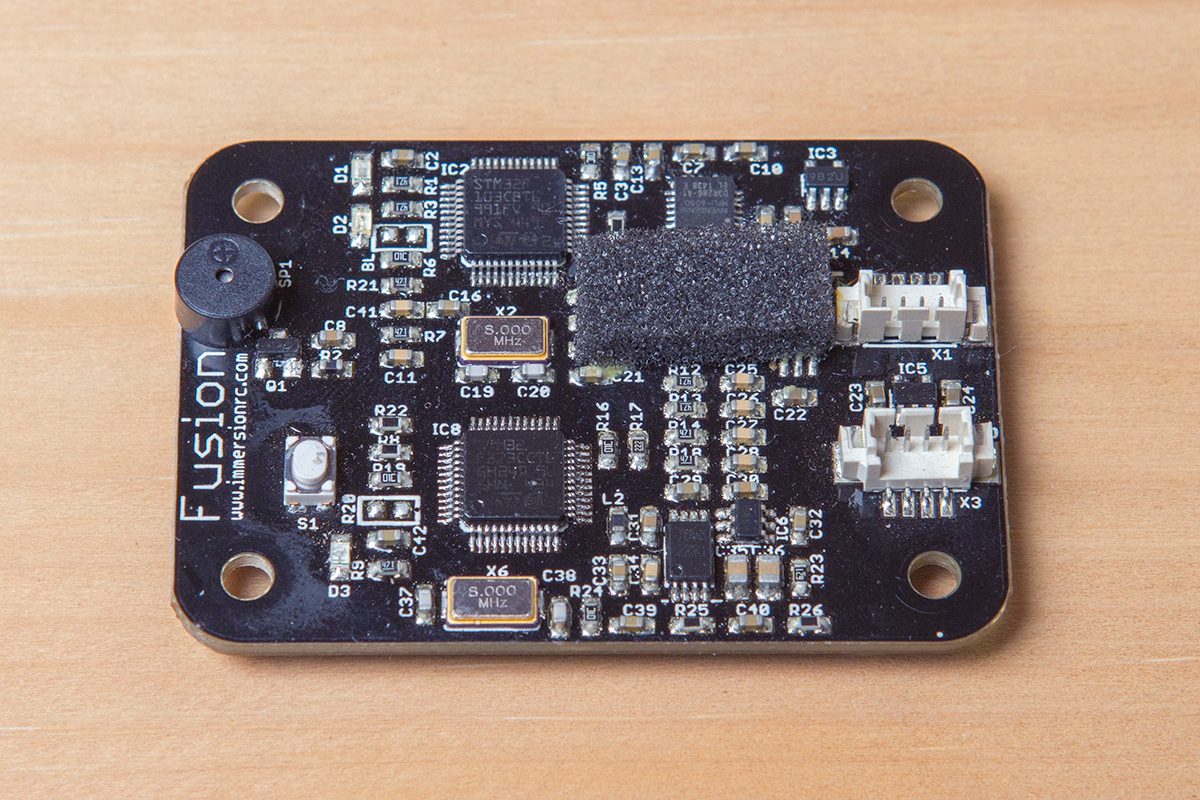
The brain of the beast revealed – the Fusion. Aptly named because it combines the flight controller and OSD into one board. Notice the two separate STM32 processors. There’s a barometric sensor under the bit of foam. Directly above is the MPU-6050 IMU chip.
I’m not sure what the two connectors are for. Presumably they’re serial interfaces for the ARM processors.
The flight controller uses Cleanflight and can be updated using the Naze32 profile, so I assume the architecture is basically a clone of the Naze32 board.
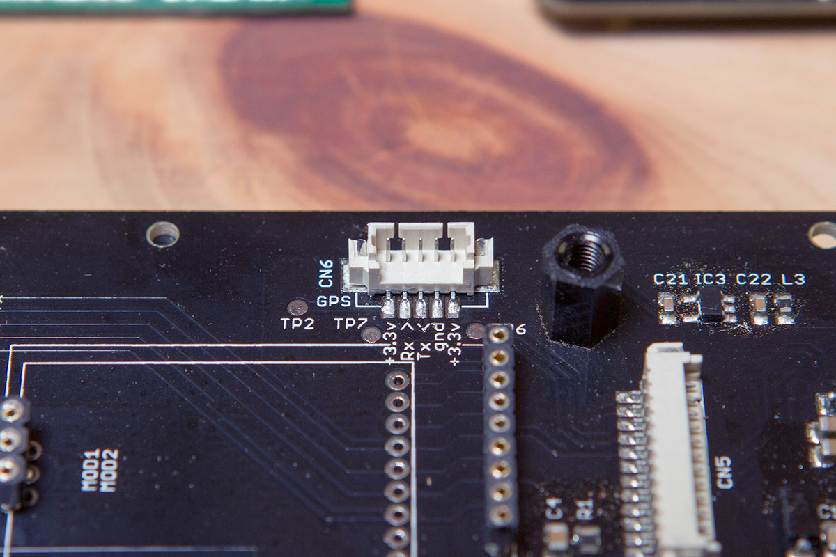
What do we have here? There’s a connector labeled GPS. Unfortunately the OSD doesn’t seem to support displaying any GPS information at the moment, but they obviously have thought about it so maybe in a future update. I need to connect my GPS here and see if Cleanflight will recognize it, but I haven’t gotten around to it yet. Will update soon!
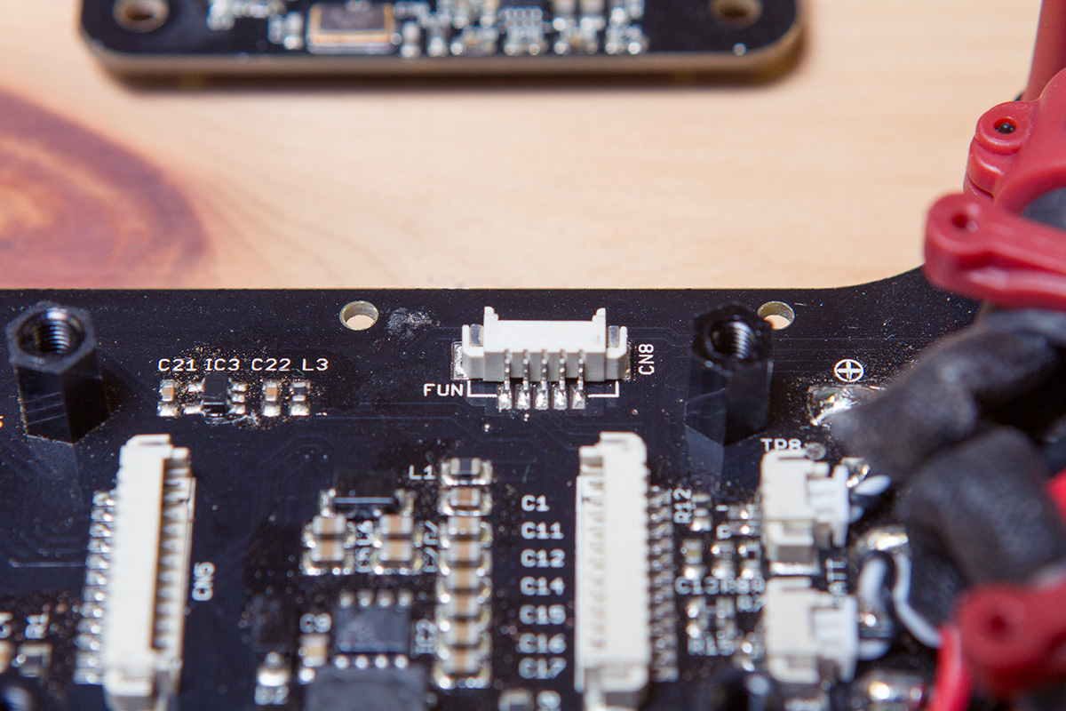
There’s also a connector labeled FUN. The pins aren’t labeled so I’m not sure about this one. I guess it could mean ‘Function’ and be a debug port or something, but I’m going to hold on to hope that there’s something fun waiting to plug in here.
That’s it for this time! I haven’t got much flight time on this machine yet, but so far it’s been fun to fly and seems like a solid contender in the 250mm class. I’ll know more once I crash it a few times 💥😁